


- SN74LS14DRE4 - 集成电路(IC) > 逻辑 > 门和反相器
- LM324KAPWRG4 - 集成电路(IC) > 线性 > 放大器 > 仪器,运算放大器,缓冲器
- CY74FCT821ATSOCTG4 - 逻辑 - 触发器
- BQ26150DCKR - 集成电路(IC) > 电源管理(PMIC) > 电池管理
- LM1949N - 集成电路(IC) > 电源管理(PMIC) > 电源管理 - 专用
- SN65LVDS93DGG - 集成电路(IC) > 接口 > 串行器,解串器
- LM2745-19AEVAL - 开发板,套件,编程器 > 评估板 > DC/DC 和 AC/DC(离线)SMPS 评估板
- LM3S1N11-IBZ50-C1T - 嵌入式 - 微控制器
- TLV75512PDBVR - 集成电路(IC) > 电源管理(PMIC) > 稳压器 - 线性
- LMH6514SQ/NOPB - 集成电路(IC) > 线性 > 放大器 > 仪器,运算放大器,缓冲器
- LMR66420MC5RXBRQ1 - 集成电路(IC) > 电源管理(PMIC) > 稳压器 - DC-DC 开关稳压器
- LP2960AIMX-5.0/NOPB - 集成电路(IC) > 电源管理(PMIC) > 稳压器 - 线性
- TL072CPS - 集成电路(IC) > 线性 > 放大器 > 仪器,运算放大器,缓冲器
- TPS7201QPW - 集成电路(IC) > 电源管理(PMIC) > 稳压器 - 线性
- TPS2301IPWR - 集成电路(IC) > 电源管理(PMIC) > 热插拔控制器
- TPS65262EVM-619 - 开发板,套件,编程器 > 评估板 > DC/DC 和 AC/DC(离线)SMPS 评估板
- AM2632CNDFHAZCZR - 集成电路(IC) > 嵌入式 > 微控制器
- LM2904DGKRG4 - 集成电路(IC) > 线性 > 放大器 > 仪器,运算放大器,缓冲器
- UCC2897APWR-AU - 未分类 > 未分类
- SNJ54LS669J - 集成电路(IC) > 逻辑 > 计数器,除法器


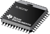
TL16C2752 - 具有 64 字节 FIFO 的双路 UART
TL16C2752是TI德州仪器公司的一款无产品,TL16C2752是具有 64 字节 FIFO 的双路 UART,本站介绍了TL16C2752的封装应用图解、特点和优点、功能等,并给出了与TL16C2752相关的TI元器件型号供参考。
TL16C2752 - 具有 64 字节 FIFO 的双路 UART - 无 - UART - 德州仪器
The TL16C2752 is a speed and functional upgrade of the TL16C2552. Since they are pinout and software compatible, designs can easily migrate from the TL16C2552 to the TL16C2752 if needed. The additional functionality within the TL16C2752 is accessed via an extended register set. Some of the key new features are larger receive and transmit FIFOs, embedded IrDA encoders and decoders, RS-485 transceiver controls, software flow control (Xon/Xoff) modes, programmable transmit FIFO thresholds, extended receive and transmit threshold levels for interrupts, and extended receive threshold levels for flow control halt/resume operation.
The TL16C2752 is a dual universal asynchronous receiver and transmitter (UART). It incorporates the functionality of two independent UARTs: each UART having its own register set and transmit and receive FIFOs. The two UARTs share only the data bus interface and clock source, otherwise they operate independently. Another name for the UART function is asynchronous communications element (ACE), and these terms will be used interchangeably. The bulk of this document describes the behavior of each ACE, with the understanding that two such devices are incorporated into the TL16C2752.
Functionally equivalent to the TL16C450 on power up or reset (single character or TL16C450 mode), each ACE can be placed in an alternate FIFO mode. This relieves the CPU of excessive software overhead by buffering received and to-be-transmitted characters. Each receiver and transmitter store up to 64 bytes in their respective FIFOs, with the receive FIFO including three additional bits per byte for error status. In the FIFO mode, selectable hardware or software autoflow control features can significantly reduce program overload and increase system efficiency by automatically controlling serial data flow.
Each ACE performs serial-to-parallel conversions on data received from a peripheral device or modem and stores the parallel data in its receive buffer or FIFO, and each ACE performs parallel-to-serial conversions on data sent from its CPU after storing the parallel data in its transmit buffer or FIFO. The CPU can read the status of either ACE at any time. Each ACE includes complete modem control capability and a processor interrupt system that can be tailored to the application.
Each ACE includes a programmable baud rate generator capable of dividing a reference clock with divisors of from 1 to 65535, thus producing a 16× or 8× internal reference clock for the transmitter and receiver logic. Each ACE accommodates up to a 3-Mbaud serial data rate (48-MHz input clock). As a reference point, that speed would generate a 333-ns bit time and a 3.33-=s character time (for 8,N,1 serial data), with the internal clock running at 48 MHz and 16× sampling.
Each ACE has a TXRDY and RXRDY (via MF) output that can be used to interface to a DMA controller.
- Larger FIFOs Reduce CPU Overhead
- Programmable Auto-RTS and Auto-CTS
- In Auto-CTS Mode, CTS Controls the Transmitter
- In Auto-RTS Mode, RCV FIFO Contents, and Threshold Control RTS
- Serial and Modem Control Outputs Drive a RJ11 Cable Directly When Equipment is on the Same Power Drop
- Capable of Running With All Existing TL16C450 Software
- After Reset, All Registers Are Identical to the TL16C450 Register Set
- Up to 48-MHz Clock Rate for up to 3-Mbps (Standard 16× Sampling) Operation, or up to 6-Mbps (Optional 8× Sampling) Operation With VCC = 5 V Nominal
- Up to 32-MHz Clock Rate for up to 2-Mbps (Standard 16× Sampling) Operation, or up to 4-Mbps (Optional 8× Sampling) Operation With VCC = 3.3 V Nominal
- Up to 24-MHz Clock Rate for up to 1.5-Mbps (Standard 16× Sampling) Operation, or up to 3-Mbps (Optional 8× Sampling) Operation With VCC = 2.5 V Nominal
- Up to 16-MHz Clock Rate for up to 1-Mbps (Standard 16× Sampling) Operation, or up to 2-Mbps (Optional 8× Sampling) Operation With VCC = 1.8 V Nominal
- In TL16C450 Mode, Hold and Shift Registers Eliminate the Need for Precise Synchronization Between the CPU and Serial Data
- Programmable Baud-Rate Generator Allows Division of Any Input Reference Clock by 1 to (216 – 1) and Generates an Internal 16× Clock
- Standard Asynchronous Communication Bits (Start, Stop, and Parity) Added to or Deleted From the Serial Data Stream
- 5-V, 3.3-V, 2.5-V, and 1.8-V Operation
- Independent Receiver Clock Input
- Transmit, Receive, Line Status, and Data Set Interrupts Independently Controlled
- Fully Programmable Serial Interface Characteristics
- 5-, 6-, 7-, or 8-Bit Characters
- Even-, Odd-, or No-Parity Bit Generation and Detection
- 1-, 1 =-, or 2-Stop Bit Generation
- Baud Generation (DC to 1 Mbit/s)
- False-Start Bit Detection
- Complete Status Reporting Capabilities
- 3-State Output TTL Drive Capabilities for Bidirectional Data Bus and Control Bus
- Line Break Generation and Detection
- Internal Diagnostic Capabilities
- Loopback Controls for Communications Link Fault Isolation
- Break, Parity, Overrun, and Framing Error Simulation
- Fully Prioritized Interrupt System Controls
- Modem Control Functions (CTS, RTS, DSR, DTR, RI, and DCD)
- Available in 44-Pin PLCC (FN) or 32-Pin QFN (RHB) Packages
- Each UART’s Internal Register Set May Be Written Concurrently to Save Setup Time
- Multifunction (MF) Output Allows Users to Select Among Several Functions, Saving Package Pins
- APPLICATIONS
- Point-of-Sale Terminals
- Gaming Terminals
- Portable Applications
- Router Control
- Cellular Data
- Factory Automation
- MSP430FR6922 - MSP430FR697x(1)、MSP430FR6 87x(1)、MSP430FR692x(1)、MSP430FR682x(1) MCU
- SN54LS20 - 双路 4 输入正与非门
- TPS62691 - 采用芯片级封装的 600mA、4MHz、2.2V 高效降压转换器
- SN74ALS251 - 具有三态输出的双路 8 选 1 数据选择器/多路复用器
- TPS74901 - 单路输出 LDO、3.0A、可调节 (0.8 至 3.6V)可编程软启动
- TL751L12 - 具有关断功能的低压降 (LDO) Pnp 小电流电压稳压器
- SN54AC00 - 四路 2 输入正与非门
- TPS3106-EP - Enhanced Military Plastic Ultra-Low Supply-Current/Supply-Voltage Supervisory Circuits
- REF3225-EP - REF3212-EP, REF3220-EP, REF3225-EP, REF3230-EP, REF3233-EP, REF3240-EP
- SN54HC74-SP - 具有清零和预设功能的双路 D 类上升沿触发器

